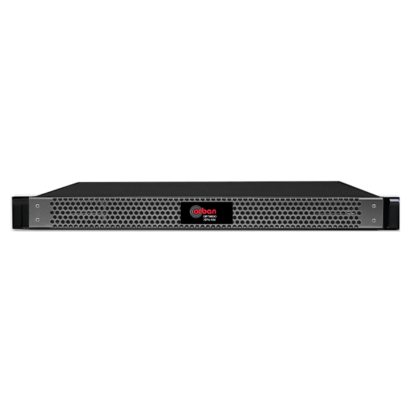
Our 5700i offers the proven OPTIMOD sound in a compact, cool-running 1U system at an affordable price. It provides stereo enhancement, equalization, AGC, multiband compression, low-IM peak limiting, stereo encoding, and composite limiting – everything that you need to compete in your market.
More than 20 excellent sounding, format-specific factory presets get you started. Although the factory presets are fully competent “out of the box,” you can customize them with easy one-knob LESS-MORE control or with more than 60 advanced controls whose versatility will satisfy even the most finicky on-air sound designer. If you have created custom presets for Optimod-FM 8500, 8400, 8300, 5500, or 5300, you’ll find that they import perfectly into the 5700i, retaining your carefully designed sound.
Independent Processing for FM and digital radio
The FM and digital media processing paths split after the 5700i’s stereo enhancer and AGC. There are two equalizers, multiband compressors, and peak limiters, allowing the analog FM and digital media processing to be optimized separately. The bottom line? Processing that optimizes the sound of your FM channel while punching remarkably crisp, clean, CD-like audio through to your digital channel audience.
Versatility Doesn’t Stop With Sound
If you choose to use the 5700i’s superb DSP-based stereo encoder and composite limiter, be assured that they deliver an FM analog signal that is always immaculately clean and perfectly peak limited, with full spectral protection of subcarriers and RDS/RBDS regardless of the amount of composite limiting.
The 5700i includes a “ratings encoder loop-through” connection. This allows a ratings encoder with an AES3 digital input and output to be inserted between the output of the AGC, before the analog-FM and HD processing paths split or between the output of the audio processing and the input to the stereo encoder. This keeps the audio level driving the ratings encoder as high as possible, minimizing the number of “low audio level” alarms that the ratings encoder generates.
For our European customers, a second-generation ITU BS 412 multiplex power controller smoothly and naturally complies with the standard.
The 5700i includes a full-featured RBS/RBDS generator at no additional charge. The generator supports dynamic PS. It can be controlled via the 5700i presets and an ASCII terminal server that can be connected to automation to support displaying title and artist.
Controllable
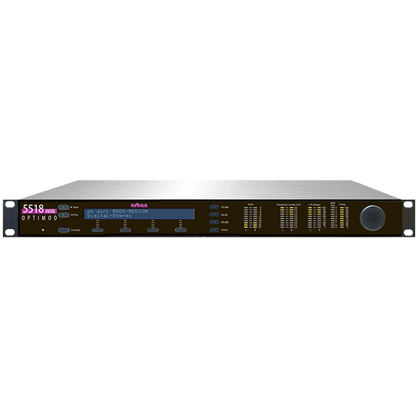
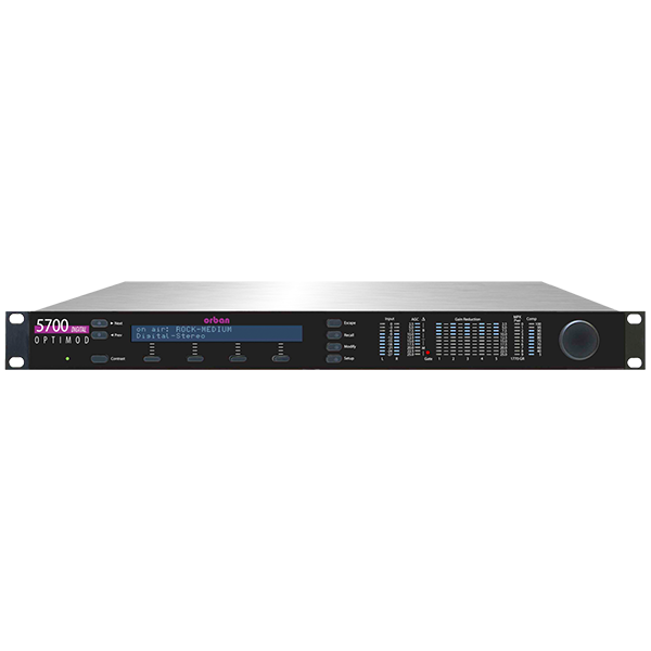
The front-panel display includes a 2×40-character LCD and LED bargraphs that show all metering functions of the processing structure (Two-Band or Five-Band) in use. The metering is always visible while you are adjusting the processor. Navigation is by dedicated buttons, soft buttons (whose functions are context-sensitive), and a large rotary knob.
Ethernet connectivity is standard, as is an easy to use PC remote control application that runs on Windows XP and higher and that can control many 5700i units on a TCP/IP network. Additionally, programmable contact-closure (GPI) control plus ACSII terminal control via the 5700i’s RS232 serial and Ethernet ports together give you total freedom to interface the 5700i with your facility’s remote control infrastructure, whatever it might be. SNMP support offers yet another way to control and monitor the 5700i’s operation via your network.
Audio Processor Quick Setup
Like the other OPTIMODs, the 5700i provides a guided, systematic procedure for setup.
Factory Presets & LESS-MORE Control
With a selection of factory presets and the simple LESS-MORE Control you can easily create your own signature sound. Orban is happy to help you find the perfect setup for your station.
Four Processing Structures
The 5700i features four Audio Processing Structures which are Optimum Five-Band (or “Multiband”; 20 ms delay) for a consistent, “processed” sound, free from undesirable side effects, Ultra-Low-Latency Five-Band (5 ms delay) for environments where talent monitors live off-air and they object to the delay of Optimum Five-Band, Low-Latency Five-Band (12 ms delay), and Two-Band for a transparent sound that preserves the frequency balance of the original program material.
“True Peak” Control
“True Peak” Control is available for the digital radio processing with an accuracy of better than 0.5 dB. For typical program material, accuracy is 0.2 dB.
ITU BS-412 Multiplex Power Control
A defeatable, program-adaptive multiplex power limiter can unobtrusively control the multiplex power according to ITU-R BS412 standards.
ITU-R BS.1770-3+ Loudness Control
Loudness Control is available for digital radio and analog radio processing chains in countries that enforce a BS.1770 loudness limit on digital and/or analog radio broadcasts.
Low-Delay DJ Monitor Output
The 5700i offers a low-delay monitor output which takes the audio from multiband compressor output and has an approximate delay of 4 ms. This allows the talent/DJ to comfortably monitor the processed audio off-air with headphones.
10 MHz Reference Input
A 10 MHz reference input allows the stereo pilot tone frequency and digital composite output sample rate to be locked to a 10 MHz reference signal (like GPS), facilitating single-frequency-network (SFN) and near-single-frequency-network (N-SFN) operation.
RDS
The 5700i has a built-in full-featured RDS/RBDS generator that supports static and dynamic RDS values.
Bypass Test Mode and Tone Generator
A Bypass Test Mode can be invoked locally, by remote control or by automation to perform a broadcast system test or to compare easily original and processed sound. A built-in line-up tone generator facilitates quick and accurate level setting.
SNMP Support
The SNMP (Simple Network Management Protocol) feature allows you to monitor your OPTIMOD’s status and to send alarm notifications via your OPTIMOD’s Ethernet connection to your network.
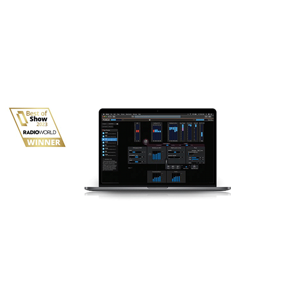
Remote Control or front panel operation
You can operate and configure the 5700i Audio Processor comfortably via the supplied Windows PC Software. Control is possible over your local network or the internet. The 5700i can also be operated easily by using its front panel and display.
Except as noted in the text, specifications apply for measurements from analog left/right in- put to stereo composite output and to FM analog left/right output.
Frequency Response (Bypass Mode): Follows standard 50μs or 75μs pre-emphasis curve ±0.10 dB, 2.0 Hz–15 kHz. Analog left/right output and digital output can be user- configured for flat or pre-emphasized output.
Noise: Output noise floor will depend upon how much gain the processor is set for (Limit Drive, AGC Drive, Two-Band Drive, and/or Multi-Band Drive), gating level, equalization, noise reduction, etc. The dynamic range of the A/D Converter, which has a specified overload-to–noise ratio of 110 dB, primarily governs it. The dynamic range of the digital signal processing is 144 dB.
Total System Distortion (de-emphasized, 100% modulation): <0.01% THD, 20 Hz–1 kHz, rising to <0.05% at 15 kHz. <0.02% SMPTE IM Distortion.
Total System L/R Channel Separation: >50 dB, 20 Hz – 15 kHz; 60 dB typical.
Polarity (Two-Band and Bypass Modes): Absolute polarity maintained. Positive-going signal on input will result in positive-going signal on output when HD Polarity and FM polarity controls are set to POSITIVE.
Processing Sample Rate: The 5700i is a “multirate” system, using internal rates from 64 kHz to 512 kHz as appropriate for the processing being performed. Audio clippers oper- ate at 256 kHz (and are anti-aliased), while the composite limiter operates at 512 kHz.
Peak Control at HD Output: The true peak limiter is oversampled at 256 kHz, yielding a worst- case overshoot of 0.5 dB at the analog output and for all output sample rates. (To achieve this performance at 32 kHz output sample rate, it is necessary to set the 5700i’s HD lowpass filter cutoff frequency to 15 kHz.)
Processing Resolution: Internal processing has 24 bit (fixed point) or higher resolution.
Defeatable Analog FM Processing delay: 0.27 to 16.384 seconds, adjustable in one- sample increments at 64 kHz sample rate to allow the delays of the analog and digital paths in the HD Radio system to be matched at the receiver output.
Minimum Processing Delay: Processing structure dependent. Typically 17 ms for normal latency Five-band, 13 ms for low-latency Five-band, 3.7 ms for ultra-low-latency Five- band, and 17 or 22 ms for 2-band, depending on crossover structure chosen.
Configuration: Stereo.
Impedance: >10kΩ load impedance, electronically balanced1.
Nominal Input Level: Software adjustable from –9.0 to +13.0 dBu (VU).
Maximum Input Level: +27 dBu.
Connectors: Two XLR-type, female, EMI-suppressed. Pin 1 chassis ground, Pins 2 (+) and 3 electronically balanced, floating and symmetrical.
A/D Conversion: 24 bit 128x oversampled delta sigma converter with linear-phase anti-aliasing filter.
Filtering: RFI filtered, with high-pass filter at 0.15 Hz.
Configuration: Stereo. Flat or pre-emphasized (at 50μs or 75μs), software-selectable.
Source Impedance: 600Ω or greater, balanced or unbalanced. Termination not required or recommended.
Output Level (100% peak modulation): Adjustable from –6 dBu to +24 dBu peak, into 600Ω or greater load, software-adjustable.
Signal-to-Noise: >= 90 dB unweighted (Bypass mode, de-emphasized, 20 Hz–15 kHz bandwidth, referenced to 100% modulation).
L/R Crosstalk: <= –70 dB, 20 Hz–15 kHz.
Distortion: <= 0.01% THD (Bypass mode, de-emphasized) 20 Hz–15 kHz bandwidth.
Connectors: Two XLR-type, male, EMI-suppressed. Pin 1 chassis ground, Pins 2 (+) and 3 electronically balanced, floating and symmetrical.
D/A Conversion: 24 bit 128x oversampled, with high-pass filter at 0.15 Hz (–3 dB).
Filtering: RFI filtered.
Configuration: Stereo per AES3 standard, 24 bit resolution, software selection of stereo, mono from left, mono from right or mono from sum.
Sampling Rate: 32, 44.1, 48, 88.2, or 96 kHz, automatically selected.
Connector: XLR-type, female, EMI-suppressed. Pin 1 chassis ground, pins 2 and 3 transformer balanced and floating, 110Ω impedance.
Input Reference Level: Variable within the range of –30 dBFS to –10 dBFS.
J.17 De-emphasis: Software-selectable.
Filtering: RFI filtered.
Configuration: Two outputs, each stereo per the AES3 standard. The outputs can be independently set to emit the analog FM processed signal, the digital radio processed signal, or the low-delay monitor signal. The FM processed signal can be configured in software as flat or pre-emphasized to the chosen processing pre-emphasis (50μs or 75μs). The digital radio processing chain receives the output of the multiband limiter and processes it through a look-ahead true peak limiter that operates in parallel with the main FM peak limiting system. The DR and FM signals are always simultaneously available. Each output can apply J.17 pre-emphasis if desired.
Sample Rate: Internal free running at 32 kHz, 44.1 kHz, 48 kHz, 88.2 kHz, or 96 kHz, selected in software. (Use 44.1 kHz or higher for best peak control.) Can also be synced to the AES3 SYNC input or the AES3 digital input at 32 kHz, 44.1 kHz, 48 kHz, 88.2 kHz, and 96 kHz, as configured in software.
Word Length: Software selected for 24, 20, 18, 16 or 14-bit resolution. First-order highpass noise-shaped dither can be optionally added, dither level automatically adjusted appropriately for the word length.
Connector: XLR-type, male, EMI-suppressed. Pin 1 chassis ground, pins 2 and 3 trans- former balanced and floating, 110Ω impedance.
Output Level (100% peak modulation): –20.0 to 0.0 dBFS software controlled.
Filtering: RFI filtered.
Frequency Response (Digital Audio Output (from Digital Radio Processing Chain)): For output sample rates of 44.1 kHz and above, the frequency response from input to DR-configured output is ±0.10 dB, 2.0 Hz – 20 kHz; flat or with J.17 pre-emphasis applied. The user may specify lowpass filtering to constrain the bandwidth to 15, 16, 17, 18, or 19 kHz.
Relative Time Delay between FM and HD Outputs: Depends on setting of analog processing channel diversity delay. Once set, this delay is constant regardless of processing preset in use.
Configuration: Accepts 1x wordclock or 10 MHz reference signals, automatically selected. The DSP master clock can be phase-locked to these signals, which in turn phase-locks the 19 kHz pilot tone frequency, facilitating singe-frequency network operation. The digi- tal output sample frequency can also be locked to these signals.
Level: Unit will lock to 1x wordclock and 10 MHz squarewaves and sinewaves having a peak value of 0.5 V to 5.0 V.
Connector: BNC female, grounded to chassis, non-terminating to allow reference signals to be looped through via an external BNC “tee” connector (not supplied).
Configuration: The Wordclock/10 MHz Sync Reference can also be configured as an AES3id digital audio input to drive the input of the stereo encoder. This facilitates a “rat- ings encoder loop-through” connection, where the input of the ratings encoder is driven from one of the 5700i’s AES3 outputs and the encoder’s output is returned to the AESid input.
Connector: BNC female, grounded to chassis, terminated with 75Ω. For short cable runs, there is usually no problem in driving this with an AES3 (110Ω) signal. If the cable is long enough to cause digital audio reception errors due to impedance m.ismatch, a 110Ω/75Ω transformer should be placed in-line.
Configuration: Two outputs, each with an independent software-controlled output level control, output amplifier and connector.
Source Impedance: 0Ω voltage source or 75Ω, jumper-selectable.
Load Impedance: 37Ω or greater. Termination not required or recommended.
Maximum Output Level: +16.0 dBu (13.82Vp-p).
Pilot Level: Adjustable from 6.0% to 12.0%, software controlled.
Pilot Stability: 19 kHz, ±1.0 Hz (10 degrees to 40 degrees C).
D/A Conversion: 24-bit
Signal-to-Noise Ratio: >= 85 dB (Bypass mode, de-emphasized, 20 Hz – 15 kHz band- width, referenced to 100% modulation, unweighted). Distortion: <= 0.02% THD (Bypass mode, de-emphasized, 20 Hz – 15 kHz bandwidth, referenced to 100% modulation, unweighted).
Stereo Separation: >50 dB, 20 Hz – 15 kHz; 60 dB typical.
Crosstalk-Linear: <= –80 dB, main channel to sub-channel or sub-channel to main channel (referenced to 100% modulation).
Crosstalk-Non-Linear: <= –80 dB, main channel to sub-channel or sub-channel to main channel (referenced to 100% modulation).
38 kHz Suppression: >= 70 dB (referenced to 100% modulation).
76 kHz & Sideband Suppression: >= 80 dB (referenced to 100% modulation).
Pilot Protection: 60 dB relative to 9% pilot injection, ±250 Hz (up to 2 dB composite proc- essing drive).
Subcarrier Protection (60-100 kHz): >= 70 dB (referenced to 100% modulation; with up to 2 dB composite limiting drive; measured with 800 line FFT analyzer using “maximum peak hold” display).
57 kHz (RDS/RBDS) Protection: 50 dB relative to 4% subcarrier injection, ±2.0 kHz (up to 2 dB composite processing drive). Connectors: Two BNC, shell connected to chassis ground, EMI suppressed.
Maximum Load Capacitance: 0.047 microfarad (0Ω source impedance). Maximum cable length of 100 feet/30 meters RG–58A/U.
Filtering: RFI filtered.
Configuration: Two subcarrier inputs sum directly into composite baseband outputs; COMPx LVL control settings have no effect on the absolute subcarrier levels.
Impedance: 600Ω
SCA Sensitivity: Variable from <100 mV p-p to >10 V p-p to produce 10% injection assuming 100% modulation = 4 V p-p at the 5700i’s composite outputs. Rear-panel accessible PC-board-mounted trim pots allow user to adjust the sensitivities of the two SCA in- puts.
Connectors: Two BNC, shell connected to chassis ground, EMI suppressed.
19 kHz Pilot Reference: SCA2 input can be re-jumpered to provide a 19 kHz pilot reference output.
Supported Computer and Operating System: IBM-compatible PC running Microsoft Windows® 2000 (SP3 or higher) XP, Vista, millennium, 7 , 8, 8.1 or 10
Configuration: TCP/IP protocol via direct cable connect, modem, or Ethernet interface. Suitable null modem cable for direct connect is supplied. Modem and other external equipment is not supplied.
Serial Connector: RS–232 on DB–9 male connector, EMI-suppressed. Uses PPP to pro- vide for direct or modem connection to the 5700i PC Remote application.
Ethernet Connector: Female RJ45 connector for 10 Mbps and higher networks using CAT5 cabling. Native rate is 100 Mbps. Provides for connection to the 5700i PC Re- mote application through either a network, or, using a crossover Ethernet cable, directly to a computer.
Ethernet Networking Standard: TCP/IP.
Configuration: Eight (8) inputs, opto-isolated and floating.
Voltage: 6–15V AC or DC, momentary or continuous. +12VDC provided to facilitate use with contact closure.
Connector: DB–25 male, EMI-suppressed.
Control: User-programmable for any eight of user presets, factory presets, bypass, test tone, stereo or mono modes, analog input, digital input.
Filtering: RFI filtered.
Circuit Configuration: Two NPN open-collector outputs.
Voltage: +15 volts maximum. Do not apply negative voltage. When driving a relay or other inductive load, connect a diode in reverse polarity across the relay coil to protect the driver transistors from reverse voltage caused by inductive kickback.
Current: 30 mA maximum
Indications: Tally outputs can be programmed to indicate a number of different operational and fault conditions, including Input: Analog, Input: Digital, Analog Input Silent, AES In- put Silent, and AES Input Error.
Voltage: 85–264 VAC, 50–60 Hz, <30 VA.
Connector: IEC, EMI-suppressed. Detachable 3-wire power cord supplied.
Fuse: 2.5A 20mm Quick Acting HBC, mounted on the power supply circuit board.
Grounding: In order to meet EMI standards, circuit ground is hard-wired to chassis ground.
Safety Standards: ETL listed to UL standards, CE marked.
Operating Temperature: 32° to 122° F / 0° to 50° C for all operating voltage ranges.
Humidity: 0–95% RH, non-condensing.
Dimensions (W x H x D): 19” x 1.75” x 14.25” / 48.3 cm x 4.5 cm x 36.2 cm. One rack unit high.
Humidity: 0–95% RH, non-condensing.
RFI/EMI: Tested according to Cenelec procedures. FCC Part 15 Class A device.
Shipping Weight & Dimensions: 18 lbs / 8.2 kg – 23″ x 23″ x 6″
Five Years, Parts and Service: Subject to the limitations set forth in Orban’s Standard Warranty Agreement.
Because engineering improvements are ongoing, specifications are subject to change without notice.